

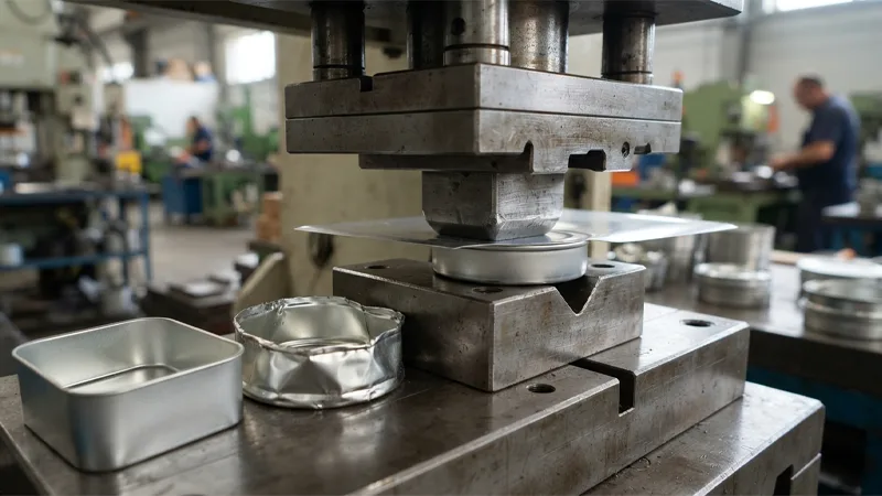

Tin packaging tooling goes through repeated forming, cutting, bending, drawing, curling, and embossing cycles during production. With each cycle, the working surfaces of dies, punches, cutting edges, curling tools, and other forming components are exposed to contact, friction, and forming loads.
The change is usually gradual rather than sudden. A cutting edge may begin producing a heavier burr before the blank dimension moves outside the specification. A forming surface may develop wear that is difficult to see but still shifts a wall or flange dimension. In a curling operation, a small change in the working surface can eventually show up as a difference in the lid-to-body fit.
For custom tin boxes, this makes tooling condition part of dimensional control rather than a separate maintenance issue. Material thickness and temper, machine alignment, feeding position, lubrication, forming conditions, measurement methods, and tooling condition can all contribute to dimensional variation.
This article looks at how tin packaging tool wear develops, which product dimensions can be affected, how wear can influence tin box lid fit and closure force, and how manufacturers can distinguish tooling problems from material or machine-related variation.
Table of Contents
What Is Tin Packaging Tool Wear?
Tool wear is the gradual change in a tooling surface or cutting edge after repeated production contact. It does not always begin with an obvious defect.
The wear mechanism depends on the tool material, tinplate properties, forming pressure, sliding contact, lubrication, surface condition, production quantity, and tool geometry. The same production run can also produce different wear behavior at different tooling locations.
A cutting edge may lose its sharp profile and begin producing more burrs. A forming die can develop wear on a contact surface, changing the way the sheet moves through the forming area. A curling tool can gradually change the profile of the rolled edge. A punch can also develop dimensional changes on surfaces that repeatedly contact the tinplate.
What matters in production is not simply whether a tool has some visible wear. The more useful question is whether the worn area is controlling a product dimension or feature that affects the finished container.
How Die Wear Affects Tin Box Dimensions
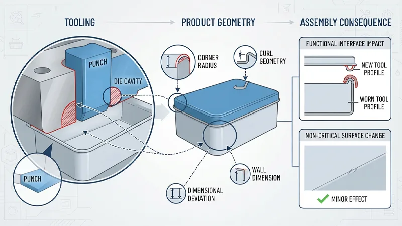
A tooling surface controls part of the final geometry. Once that surface changes, the sheet may no longer be formed to exactly the same profile.
The result depends on where the wear occurs. A change in a forming radius can alter the corner profile. Wear on a curling surface can change the curl geometry. A change in a punch or die surface can shift a wall dimension, flange position, or formed depth.
Not every dimensional change has the same production consequence. A small change on a non-functional surface may have little effect on assembly. The same amount of change at a lid, flange, curl, or body interface can affect how two components engage.
For this reason, die inspection should be linked to the dimensions controlled by each working surface. The tooling drawing, product drawing, and inspection results should be considered together rather than treating tool wear as a purely visual condition.
Types of Tool Wear in Tin Packaging Manufacturing
Wear does not occur in the same way across the entire tooling system.
Cutting tools are mainly concerned with the condition of the cutting edge. Forming dies and punches are exposed to repeated contact with the sheet and can develop wear on their working surfaces. Curling tools control the rolled edge and can gradually lose part of the geometry that produces the required curl. Embossing tools can change the depth or definition of formed features.
The first inspection point should therefore be the area of the tool that controls the affected product feature.
Cutting Tool Wear
The cutting operation determines the blank that enters the following forming stages. Once the cutting edge starts to wear, the cut edge can become rougher and burrs can increase.
A worn cutting edge can also change the blank dimension. That matters because the blank is not an isolated feature; it establishes how much material is available for the next forming operation.
If the blank becomes too large or too small, subsequent forming may show dimensional changes even when the forming die itself has not changed. When a forming problem appears, the blank should therefore be checked before the cause is assigned to the forming tooling.
Forming Die Wear
Forming dies control the geometry created during stamping, bending, or drawing. Their working surfaces determine how the tinplate moves and where the material is constrained.
Wear in these areas can affect wall dimensions, corner geometry, flange position, or formed depth. The exact result depends on the die profile, clearance, material condition, and forming sequence.
Inspection should focus on the surfaces responsible for the affected dimensions. If the product dimension has shifted but the tool condition appears unchanged, machine alignment, setup, material properties, and measurement conditions should also be checked.
Curling Tool Wear
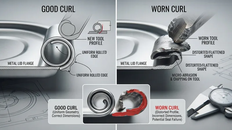
Curling tools form the rolled edges used on many tin packaging components. Because the curl can be part of the closure interface, its geometry matters beyond appearance.
A small change in the curling surface can alter the curl diameter, position, or profile. The resulting lid may still look acceptable but engage differently with the body.
For this reason, inspection of a curling tool should not stop at visual appearance. Check the curl-related dimensions on the finished component and compare them with the lid or body dimensions that control the assembled fit.
Why Tool Wear Can Change Gradually
Tool wear normally develops over repeated production contact. A tool can produce parts close to the target dimension at the beginning of a run and gradually move away from that condition as production continues.
The change may be small enough to remain inside the tolerance for some time. For example, a closure-related dimension might start near the middle of the specification range and then move steadily toward one limit.
The parts are still technically acceptable at that stage, but the process is no longer centered in the same place.
If production continues without checking the trend, the dimension can eventually cross the tolerance limit. More importantly, a functional fit can sometimes deteriorate before an individual measurement becomes obviously out of specification.
For this reason, repeated measurements are more informative than a single pass-or-fail result when investigating possible tooling wear.
Tool Wear and Tin Box Dimensional Variation
A dimensional shift should not automatically be classified as tool wear.
Material thickness, temper, mechanical properties, surface condition, machine alignment, feeding position, forming conditions, temperature, lubrication, and the measurement method can all influence the result.
The timing of the change is useful when separating these causes.
If a dimension gradually moves in one direction as production quantity increases, tooling wear becomes one possible contributor. If the change appears immediately after a material lot change, the incoming material should be checked. If the shift starts after a machine adjustment, the setup should be reviewed.
Production records make this comparison much easier. Measurements should be associated with production time or quantity, material batch, machine setup, and tooling condition where practical.
Tool Wear and Lid Fit
Lid fit is particularly sensitive because the lid and body are usually formed as separate components but must work together after assembly.
The body may be controlled by an outside dimension while the lid is controlled by an inside dimension. Flange dimensions, wall geometry, curl geometry, and the relative position of these features all contribute to the final fit.
A change in one of these dimensions can affect the closure even when the other dimensions remain within their individual specifications.
For example, gradual wear in a curling tool can change the lid curl. The finished lid may then require more force to engage, become loose after assembly, or show inconsistent fit from one production piece to another.
This is why closure problems should be investigated as a dimensional relationship rather than by checking the lid or body in isolation.
Tool Wear and Closure Force
Closure force depends on how the lid and body dimensions interact and on the material surfaces that come into contact during closing and removal.
For friction-fit or interference-fit structures, a small change in a functional dimension can change the amount of force required to close or remove the lid. Tool wear can therefore contribute to changes in opening or closing force.
However, closure force alone does not identify the cause.
Material thickness and mechanical properties, coating condition, surface friction, assembly conditions, and other closure dimensions can also change the measured force. A higher opening force does not automatically mean that the curling tool is worn.
When closure force changes, compare the force measurement with the relevant lid and body dimensions. If both the functional dimension and closure force move in the same direction, inspection of the corresponding tooling becomes more useful.
Which Tin Packaging Dimensions Should Be Monitored?
Not every dimension needs to be checked at the same frequency.
The inspection plan should separate dimensions according to their function. Overall length and width may affect secondary packaging or product fit. Height can affect stacking and internal volume. Flange and curl dimensions can affect assembly. Lid and body dimensions can directly determine closure performance.
The product drawing should define the required dimensions and tolerances. The inspection procedure should then specify where the measurement is taken, which datum is used, what instrument is required, and under what conditions the measurement is made.
This matters because two different measurement methods can produce different results on the same feature. A dimension should be measured in a way that matches the product specification and the intended functional requirement.
Tool Wear and Functional Dimensions

A functional dimension directly affects how the container performs or how one component interacts with another.
Lid and body closure dimensions are obvious examples. Other examples may include features that determine how a bottom component joins the body or how an embossed feature fits within another component.
Not every surface requires the same tooling control. A small amount of wear on a cosmetic area may have little practical effect, while the same amount of change on a closure surface may create an assembly problem.
This distinction is useful when setting maintenance priorities. The tooling areas controlling functional dimensions should receive closer monitoring because their condition has a more direct relationship with product performance.
How to Detect Tin Packaging Tool Wear
The most useful evidence usually comes from a combination of product measurements, tooling inspection, and production records.
Dimensional inspection can show whether a controlled feature is moving away from its target. Visual inspection can identify scratches, abnormal forming marks, surface damage, or obvious changes to the tool.
Visual inspection alone is not enough to confirm functional wear. A tool can look acceptable while a controlled dimension has already begun to drift.
Production records add another layer of information. When dimensional results are recorded against production quantity, time, material batch, and tooling condition, it becomes easier to see whether a change is gradual, sudden, or linked to a specific production event.
The practical point is simple: compare the same feature over time rather than relying on one sample.
Dimensional Trend Monitoring
Trend monitoring means measuring the same feature at defined production intervals and looking at how the values move.
For a closure-related dimension, for example, measurements can be compared with both the target value and the tolerance limits. A stable process will normally remain around a consistent range. A gradual shift toward one side needs investigation even if every individual measurement is still within specification.
A trend does not prove that the tool is worn. It only shows that the process or one of its variables has changed.
The next step is to compare the dimensional trend with tooling condition, material changes, machine adjustments, and other production records. If the timing and location correspond, a tooling inspection can then be used to confirm or reject the wear hypothesis.
Tool Wear Inspection
Tool inspection should concentrate on the working surfaces that contact or control the tinplate.
Depending on the tooling, the inspection may include visual examination, dimensional checks, surface condition checks, and comparison with the original tooling specification.
Different tooling components need different inspection criteria. A cutting edge, forming punch, forming die, and curling component do not control the same features and should not be evaluated using one generic wear standard.
The maintenance record should identify the tool or component, inspection date, production quantity where applicable, observed condition, dimensional findings, and action taken.
This record becomes useful later when a similar dimensional shift appears on another production run.
Tool Wear Versus Material Variation
Material variation can create a defect that looks like a tooling problem.
Tinplate thickness, temper, mechanical properties, and surface condition all influence how the sheet behaves during forming. Two material batches running through the same tooling can therefore produce different dimensional results.
When a dimensional shift appears immediately after changing material lots, check the incoming material before changing or reworking the tooling. Compare the relevant material specifications and, where necessary, verify the actual thickness and mechanical properties.
The same tooling can produce different results when the forming behavior of the material changes. Material variation and tooling wear should therefore remain separate possibilities until the production data and inspection results point to one cause.
Tool Wear Versus Machine Setup
Machine setup is another common source of dimensional change.
Tool position, alignment, stroke, feeding position, forming pressure, and other setup conditions can change the way the sheet enters and moves through the tooling.
If the tool has not been changed but the product dimension suddenly shifts, check the machine setup before concluding that the tool is worn. The timing is important: a sudden change following an adjustment points to a different cause than a slow drift over thousands of production cycles.
A useful production record should connect dimensional results with machine adjustments and tooling changes. This allows the investigation to establish whether the shift began after a setup change, material change, or increase in production quantity.
Tool Wear and Coating Damage
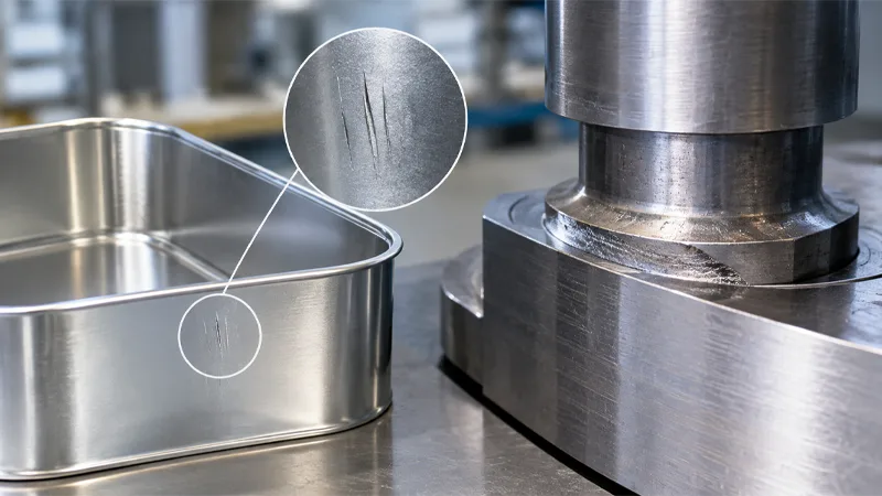
Tool condition can affect the coating and surface of tinplate during forming.
A damaged, contaminated, or rough tool surface can produce repeated scratches or marks at the same location on the finished component. Excessive friction can also change the forming condition.
However, a coating defect should not automatically be assigned to tool wear. Coating properties, curing, material surface condition, lubrication, forming strain, and handling can produce similar results.
The defect location is useful evidence. If the same mark appears repeatedly at the same position on the component, compare that location with the corresponding area of the tooling. Inspecting the contact surface can then help determine whether the tool is contributing to the defect.
Tool Wear in Embossing Operations
Embossing tools create raised or recessed features, so wear can change the depth and definition of those features over time.
Possible changes include reduced feature depth, altered dimensions, uneven definition, or positional variation. The actual effect depends on the tool geometry and forming process.
For products with specified embossing dimensions, the feature should be measured against the drawing rather than judged only by visual appearance.
A feature can still look acceptable while its depth has moved away from the required value. Where the embossing feature has a functional purpose, dimensional inspection becomes more important than visual consistency alone.
Tool Wear in Deep Drawing
Deep drawing places the material and tooling under repeated contact while the sheet moves into the die. Forming depth, material properties, tool radius, clearance, and lubrication all affect the result.
As the working surfaces change, the contact geometry can also change. Depending on where the wear occurs, the result may include dimensional variation, altered corner geometry, surface marks, or a change in forming behavior.
Both the tool and the formed component should be checked when investigating deep drawing tool wear.
A tooling inspection by itself does not show whether the wear has become functionally significant. The corresponding product dimensions and surface condition need to be measured as well.
When Should Tin Packaging Tooling Be Replaced?
There is no single production quantity that determines when every tin packaging tool must be replaced.
Tool life depends on tool material, product geometry, production volume, forming conditions, material characteristics, lubrication, maintenance, and the dimensional requirements of the product.
A tool with minor wear may continue producing acceptable parts if the controlled dimensions remain stable and within specification. Another tool may require repair or replacement sooner because the affected surface controls a critical closure dimension.
Replacement decisions should therefore be tied to defined inspection criteria. These may include dimensional drift, surface condition, repeated defects, inability to maintain the required process window, or a tooling condition that cannot be corrected through normal maintenance.
A fixed cycle count can be useful as a maintenance reference, but it should not be the only replacement criterion.
Tool Maintenance and Production Control
Tool maintenance works best when it is connected directly to production inspection.
When a recurring dimensional trend appears, inspect the tooling component responsible for that feature. If wear is confirmed, the appropriate action may be repair, adjustment, regrinding, replacement of a component, or replacement of the complete tool, depending on the tooling design.
After maintenance, first-piece inspection should be repeated. The purpose is not simply to confirm that the tool has been serviced, but to verify that the controlled product dimensions have returned to the required condition.
Maintenance records should also be kept with production and inspection data. Over time, these records can show how production quantity relates to tooling condition and when particular dimensions typically begin to move.
How Tool Wear Affects Different Tin Box Components
The effect of tool wear depends on the component being formed.
For the body, relevant changes can include wall dimensions, corner geometry, height, and flange dimensions. For the lid, inside dimensions, curl, flange, and other closure features are usually more important.
For a bottom component, tooling changes can affect the connection between the bottom and body. Embossed components may show changes in feature depth or geometry.
This is why the statement “the tooling is worn” is not specific enough for a root-cause investigation. The useful information is which tool component is worn, where the wear is located, and which product feature that area controls.
Tool Wear and Tin Packaging Quality Control
Product inspection and tooling inspection answer different questions.
Product inspection determines whether the finished component meets its dimensional, visual, and functional requirements. Tooling inspection determines whether the equipment remains in the condition required to produce those results consistently.
The two should be reviewed together when a controlled dimension begins to move.
For example, a product dimension may show a gradual shift while the tool develops a corresponding change on its working surface. Conversely, the product may change while the tool remains stable, pointing the investigation toward material, machine setup, lubrication, or another process variable.
This connection is especially important for closure-related dimensions because small dimensional changes can affect the relationship between the lid and body.
A Practical Root-Cause Approach
When a recurring defect appears, start with the defect itself rather than assuming the tooling is responsible.
First, identify exactly where the problem occurs and what the defect looks like. Determine whether it is dimensional, visual, functional, or a combination of these.
Then compare the affected measurement with previous production results. Look for the timing and direction of the change.
A gradual one-directional drift with increasing production quantity is a reason to inspect the corresponding tooling area. A sudden shift after a material lot change calls for a material check. A change that follows a machine adjustment requires a setup review.
Once the likely cause has been narrowed down, make one controlled change where possible and repeat the measurement. Avoid changing the die, machine settings, and material at the same time because doing so makes the result difficult to interpret.
The objective is to separate tooling wear from other sources of process variation and establish a clear relationship between the suspected cause and the measured defect.
Tool Wear and Preventive Maintenance
Preventive maintenance does not have to mean replacing a tool after an arbitrary number of cycles.
A more useful system combines defined inspection intervals with the tool’s previous production history. Closure-related dimensions, for example, may need more frequent product checks than dimensions with little effect on assembly.
Tooling inspection can follow a separate interval based on previous wear behavior, production quantity, and the importance of the controlled features.
The inspection frequency can then be adjusted when production data shows a consistent relationship between production quantity and dimensional drift.
This approach makes preventive maintenance a process-control activity rather than simply a replacement schedule.
Why Tooling Records Matter
Tooling records provide the history needed to investigate recurring problems.
A useful record can include the tool identification, product model, material specification, production quantity, maintenance history, dimensional inspection results, tooling condition, and repair information.
When a dimensional problem appears, these records make it possible to check whether the same tool has produced similar changes in previous production runs.
This becomes particularly useful for custom tin packaging because different product designs may use different dies, punches, curling tools, and forming sequences. Their wear behavior will not necessarily be the same.
Tin Packaging Tool Wear and Long-Term Dimensional Stability
Long-term dimensional stability means that a production process continues to produce components within the required specifications as production continues.
Tool wear can reduce this stability, but tooling is only one part of the control system.
Material control, machine setup, alignment, lubrication, measurement systems, process monitoring, and production records all influence the final result. If these factors are not tracked, it becomes difficult to determine why a dimension has moved or whether a tooling adjustment actually solved the problem.
For custom tin packaging, long-term dimensional control is therefore better managed through a combination of tooling maintenance and production data rather than by tooling inspection alone.
Conclusion
Tin packaging tool wear develops through repeated production contact and can gradually change the working geometry of cutting edges, punches, forming dies, curling tools, and embossing components.
The effect depends on where the wear occurs. Cutting edge wear can influence blank dimensions and burr formation. Forming die wear can affect walls, corners, flanges, and formed depth. Curling tool wear can change closure-related geometry. Embossing tool wear can reduce or alter the definition of formed features.
Tool wear can also contribute to tin box dimensional variation and lid-fit problems, but a dimensional shift should not automatically be treated as proof of tooling wear. Material variation, machine setup, alignment, forming conditions, lubrication, and measurement methods can produce similar changes.
A practical control system is:
Tooling Condition → Product Dimensions → Closure Fit → Functional Inspection → Tool Maintenance
The important part is the connection between these steps. Monitor functional dimensions over time, look for directional drift, compare the result with material and machine records, inspect the corresponding tooling surface, and verify the product again after any tooling adjustment or replacement.
For custom tin packaging, tooling maintenance is therefore part of dimensional and functional quality control. The objective is not simply to keep a die in service, but to keep the relationship between the tooling, formed component, and assembled container within the required production range.
FAQ
1. How does tool wear affect tin box dimensions?
Tool wear can gradually change the working geometry of a die, punch, curling tool, or cutting edge. Depending on the location of the wear, the change may appear in body dimensions, lid dimensions, corner geometry, flange dimensions, curl dimensions, formed depth, or other controlled features.
2. Can tool wear cause tin box lid fit problems?
Yes. If wear changes a dimension that controls the relationship between the lid and body, the closure condition can change. The result may be higher or lower insertion force, increased removal force, reduced engagement, a loose lid, or inconsistent fit between production pieces.
3. How can manufacturers determine whether dimensional variation is caused by tool wear?
Compare the same dimension over time and relate the measurements to production quantity, material batches, and machine setup records. A gradual shift in one direction during continued production can justify a tooling inspection. However, product measurements alone do not prove tool wear; the corresponding tooling condition should also be checked.
4. When should a tin packaging die be replaced?
There is no universal replacement cycle for all tin packaging dies. Repair or replacement should be based on tooling condition, dimensional inspection results, product requirements, recurring defects, and whether the tool can continue producing parts within the required specification.
5. Does tool wear affect the coating on tin packaging?
It can. A damaged, contaminated, or worn tooling surface may contribute to scratches, marks, or other surface defects during forming. However, coating properties, curing, material surface condition, forming strain, lubrication, and handling can produce similar defects. The defect location should be compared with the corresponding tooling area before assigning the cause to tool wear.


