

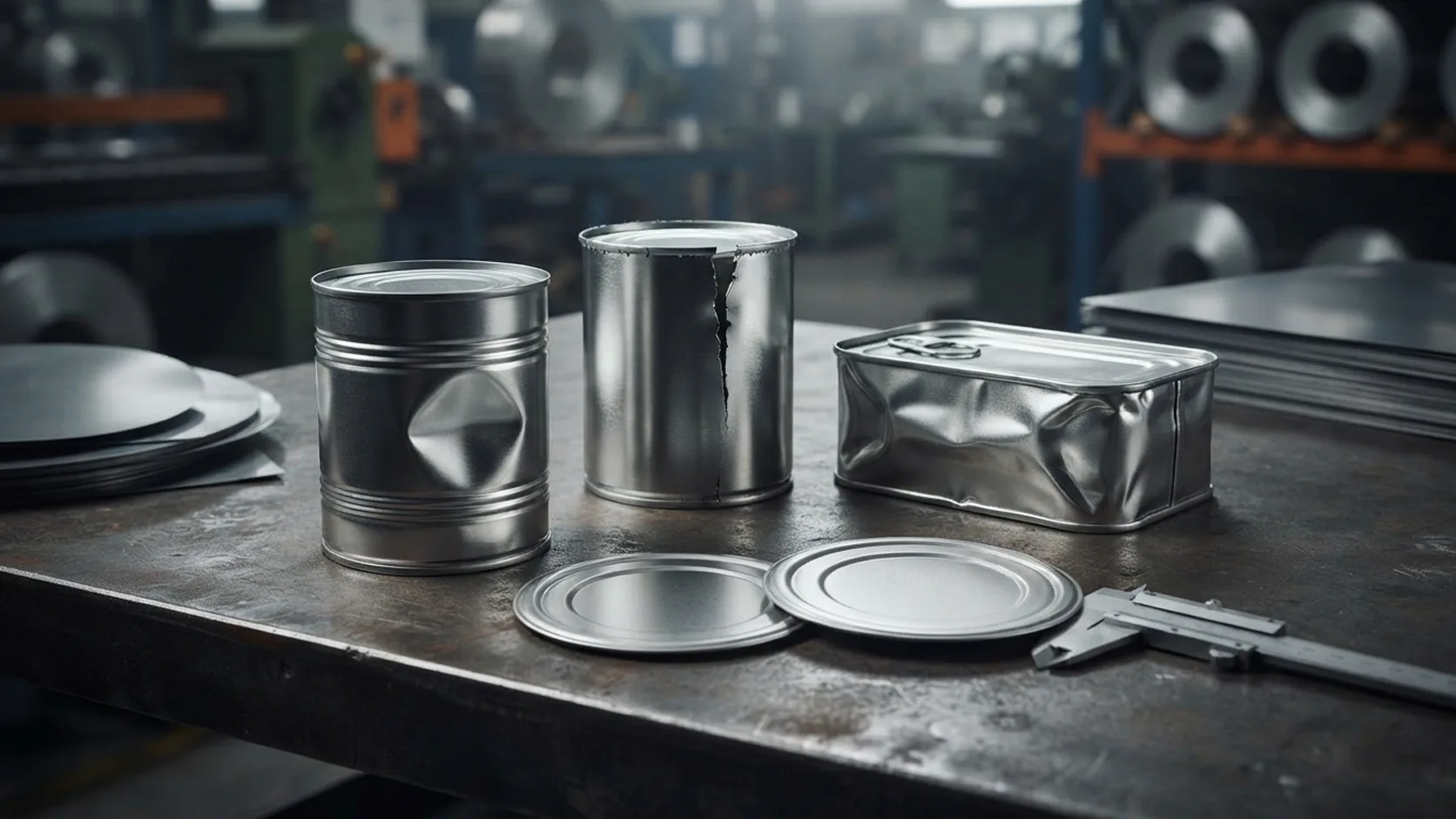

Tin packaging defects rarely come from the finished part alone. A dent may be introduced during forming, or it may appear later during stacking. A dimensional shift may come from tool wear, material variation, machine setup, or a change in the forming condition.
That distinction matters in tin box production. Correcting the wrong process can remove one visible symptom while leaving the actual cause unchanged.
Common defects include deformation, cracking, wrinkling, dimensional variation, uneven curling, denting, scratches, and coating damage. The useful starting point is not simply to name the defect. Check where it occurs, when it first appears, and whether the same pattern repeats from one part to the next.
Table of Contents
What Causes Tin Packaging Defects?
A tin box passes through several operations before it becomes a finished package. Cutting, stamping, drawing, bending, curling, embossing, assembly, printing, and handling can each introduce a different type of variation.
The material is one part of the equation. Tinplate thickness, temper, surface condition, and batch-to-batch variation can change the way the sheet behaves during forming.
Tooling has the same effect. Die clearance, punch and die geometry, corner radius, tool surface condition, guide accuracy, and wear all affect material movement.
Machine settings then determine how the tool meets the material. Feeding position, stroke, pressure, speed, lubrication, and alignment can shift the result even when the tool itself has not changed.
This is why a defect should not be traced to the first obvious variable.
A useful investigation starts with four pieces of information:
- Where is the defect?
- When does it first appear?
- Does it repeat in the same location?
- What changed before the defect appeared?
Those questions usually narrow the investigation faster than changing several machine parameters at once.
Tin Packaging Deformation
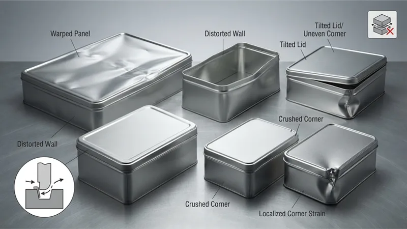
Deformation means that the component has lost its intended geometry.
On a tin box, this may show up as a warped panel, distorted wall, uneven corner, tilted lid, or local depression. The shape of the defect often gives some indication of how the load was applied.
A broad flat panel behaves differently from a corner or formed edge. Do not inspect them in the same way.
Panel Deformation
Large flat panels have limited stiffness and can deform under relatively low external loads compared with formed sections.
During production, insufficient support or uneven forming pressure can leave a panel out of plane. The problem may also develop after forming. Stacking, transfer between operations, packing pressure, and transportation can all produce a dent or warp.
The production stage is therefore worth recording.
If the panel is already distorted immediately after forming, inspect the forming support, tool contact, and machine condition. If it passes the forming inspection and becomes distorted after stacking, changing the forming parameters is unlikely to solve the problem.
Corner Deformation
Corners are more sensitive to local forming conditions because material movement changes direction around the radius.
A corner radius that is too tight for the selected material can increase local strain. Tool alignment matters as well. A worn guide post, damaged guide bush, or misalignment between punch and die can leave one corner different from the others.
When only one corner repeatedly shows the problem, compare that corner with the other three. Check the tool, alignment, radius, and finished dimensions before making a general process adjustment.
Tin Packaging Cracking
Cracking is a material failure rather than a simple surface defect. The metal has been strained beyond what the local forming condition can accommodate.
It can occur at corners, deep-drawn areas, embossed features, flange transitions, or other locations where deformation is concentrated.
For tin packaging cracking, look at the crack pattern first. A crack that always starts from the same radius suggests a different investigation from cracks that appear at random locations.
Material thickness and temper affect formability. Tool geometry controls local deformation. Lubrication and forming conditions influence friction and material flow.
Cracking at Corners
Corner cracking is commonly associated with concentrated strain.
Check the corner radius, material condition, forming depth, die clearance, and alignment. If the crack appears at a consistent point, inspect the corresponding tool surface for wear or damage.
Do not immediately increase forming pressure. More force does not necessarily improve forming; depending on the geometry, it can increase local strain and make the crack worse.
A better approach is to determine whether the material is failing because it is being stretched too far, restrained incorrectly, or forced through an unsuitable tool geometry.
Cracking Around Embossed Features
Embossing moves material locally and changes the strain distribution around the feature.
If the embossing depth is excessive for the material condition, cracking can occur around the transition rather than at the deepest point of the emboss.
The distance from the emboss to a nearby bend, corner, or flange also matters. When two forming features are too close together, the available material has less room to accommodate the deformation.
If cracks appear around the same embossed feature on every part, measure the feature depth and inspect the transition radius. Compare those results with the approved drawing and forming condition.
Tin Packaging Wrinkling
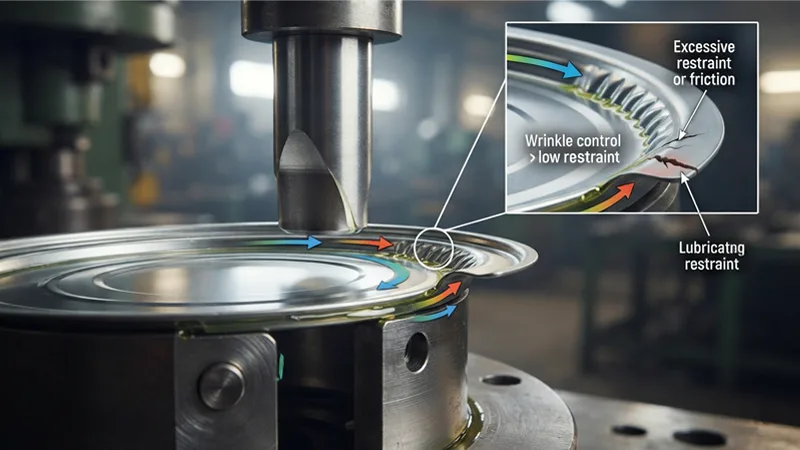
Wrinkling is usually a material-flow problem.
During drawing or forming, some areas of the sheet are compressed while material moves toward the formed section. If that material is not sufficiently controlled, it can buckle and form visible folds.
The important point is that wrinkle control and crack control can conflict. Too little restraint may produce wrinkles. Too much restraint can restrict material flow and increase the risk of tearing.
Wrinkling During Drawing
For drawing operations, check how the blank is being held and how material is entering the forming area.
Where a blankholder is used, blankholder force needs to be stable. Too little force can allow excessive material movement and wrinkling. Excessive force can increase resistance to material flow and contribute to tearing.
Lubrication also matters. A broken or uneven oil film changes friction between the sheet and tooling. Check the lubricant type, application method, coverage, and condition rather than treating lubrication as a simple on/off setting.
The same applies to forming speed and tool condition. A process that worked with one material batch may behave differently when the material condition changes.
Do not chase wrinkles by adjusting pressure blindly. Change one variable at a time and check the result for both wrinkles and cracking.
Tin Packaging Dimensional Variation
Dimensional variation becomes a quality problem when the finished component moves outside the specified range or when variation between parts becomes large enough to affect assembly.
Typical controlled dimensions include length, width, height, flange dimensions, wall dimensions, curl dimensions, and lid-to-body engagement dimensions.
The drawing should define the tolerance. A general tolerance should not replace a product-specific requirement.
Material Variation
Tinplate thickness and mechanical properties can vary within the supplier’s allowable range.
That variation can affect forming force, springback, material flow, and final geometry.
If the problem starts with a new material lot, compare the incoming material records with the previous conforming lot. Check thickness and the applicable material specification before changing the tooling.
This is particularly important when the finished dimensions shift in the same direction across a complete batch.
Springback
Springback occurs after the forming load is released and the material partially returns toward its previous shape.
It can affect wall geometry, angles, flange position, and closure dimensions.
A useful clue is consistency. If every part shows approximately the same dimensional offset after forming, springback or a stable tooling condition is more likely than random feeding variation.
Measure the affected dimension before modifying the tool. If the offset is stable, the process can be adjusted against actual measurement data rather than by visual judgment.
Tin Packaging Curling Defects
Curling creates the edge used on many tin packaging components for closure or assembly.
The curl may look acceptable from the outside while still being wrong dimensionally. Diameter, height, position, roundness, and local flattening can all affect how the mating component engages.
Common defects include uneven curl diameter, incomplete curling, irregular height, local flattening, and an inconsistent edge profile.
Uneven Curl
Start by comparing the curl at several positions around the component.
If the same section is consistently high, low, tight, or loose, check tool alignment, forming surfaces, and local tool wear.
If the position of the variation changes from part to part, inspect feeding, material positioning, and machine stability.
The curl should also be checked after assembly. A dimension that looks acceptable on the individual component may still produce poor lid fit when combined with the mating body.
Tin Packaging Denting
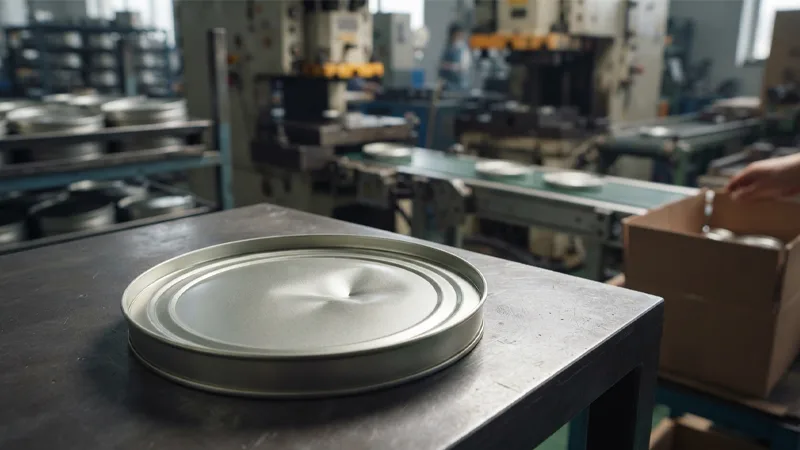
Dents are local depressions caused by impact or pressure.
They are not necessarily a forming defect.
A dent can be created at the press, during trimming or assembly, during transfer between machines, while parts are stacked, or during packing and transportation.
The simplest diagnostic step is to establish when the dent first appears.
Inspect the part immediately after the suspected operation. If it is clean at that point but damaged later, move the investigation downstream.
This prevents a common mistake in defect correction: changing the forming process to solve damage that is actually caused by handling.
Tin Packaging Coating Damage
Coating damage includes scratches, cracks, peeling, exposed metal, and local loss of coating continuity.
The damage can occur before forming, during forming, or after the component has been formed.
The coating system, curing condition, forming strain, tool surface, and handling process all need to be considered.
Coating Damage During Forming
The coating must deform with the metal substrate.
If the local forming strain exceeds the coating system’s capability, cracks or adhesion loss can appear around bends, corners, embossed features, or other highly deformed areas.
Tool condition can produce a different pattern. Contamination on a forming surface, a damaged tool edge, or excessive surface roughness can leave a repeated scratch in the same position.
The location of the scratch is useful evidence. If every part carries a mark at the same point, inspect the corresponding tool surface.
Coating Adhesion
Coating adhesion is not the same as chemical resistance.
An adhesion test evaluates how well the coating remains attached to the substrate under defined test conditions. It does not establish resistance to every food, cosmetic formulation, oil, solvent, or other product.
For tin packaging coating compatibility, the test method should reflect the intended application and the actual exposure conditions.
Tin Packaging Defects Related to Tooling
Tooling problems often leave a repeatable pattern.
A worn punch, die, curling tool, or forming surface can gradually change dimensions. A damaged surface can leave a scratch or local mark. Guide post and guide bush wear can introduce alignment changes between the upper and lower tooling.
The rate of change is also useful.
A defect that appears gradually over thousands of cycles points toward a different cause from a defect that begins immediately after a tool change or setup adjustment.
Check the tool against the last known conforming condition. Look at wear points, contact surfaces, alignment, clearances, radii, and any feature that directly controls the affected dimension.
For cutting operations, die clearance is another important variable. Clearance that is unsuitable for the material thickness can influence the cut edge, burr formation, and the load required during blanking. It should be checked against the actual material and tooling specification rather than treated as a universal percentage.
Tin Packaging Defects Related to Machine Setup
A correctly manufactured tool can still produce defective parts if the machine setup is wrong.
Feeding position is one example. In a multi-station press, a small feed pitch error can accumulate or shift a feature from its intended position. This becomes particularly important when several forming or cutting operations are performed in sequence.
Check the actual feed length and registration rather than relying only on the machine setting.
Machine alignment is another area to inspect. Uneven contact between the upper and lower tooling can produce different forming results from one side of the part to the other.
Stroke and bottom-dead-center position can also matter. If the forming depth changes, check the actual bottom-dead-center position and forming depth rather than assuming the nominal machine setting has remained unchanged.
Where pressure is involved, record the actual operating condition. Do not change pressure, speed, stroke, and lubrication simultaneously. Once several variables are changed together, it becomes difficult to identify which adjustment affected the result.
How to Analyze Tin Packaging Defects
Defect investigation works better when the part is followed through the process.
Take a defective component and establish the last operation at which it was known to be conforming.
Then compare:
Material lot → Machine → Tool → Setup → First-piece result → In-process result → Finished part
The defect pattern provides another useful clue.
A mark in exactly the same location on every part points toward a fixed contact point, tool feature, or forming condition. A defect that moves around the part suggests feeding, material positioning, handling, or process instability.
Dimensional measurements should be taken at the same time.
A visual change without dimensional movement may require a different investigation from a dimensional change accompanied by visible deformation. Do not rely on appearance alone when the drawing specifies a measurable feature.
First-Piece Inspection and Tin Packaging Defect Prevention

First-piece inspection is the point where a setup problem can be found before it becomes a production batch problem.
The inspection should follow the drawing and approved product requirements.
For a lid and body, check them as a mating pair. A lid that is individually within tolerance does not automatically guarantee correct closure.
For formed containers, typical checks include overall dimensions, height, corner geometry, flange dimensions, curl dimensions, and formed features.
Visual inspection should cover cracking, wrinkling, deformation, scratches, dents, and coating damage.
The first piece should establish a reference for the production run. When the process is adjusted later, the new result can be compared with this conforming condition instead of relying on memory.
Process Monitoring During Tin Box Production
Final inspection finds nonconforming parts. Process monitoring helps identify why the process is moving toward that condition.
The inspection frequency should match the product requirements and process stability.
For critical dimensions, record measurements over the production run rather than checking isolated pieces only. A gradual shift can indicate tool wear, material change, temperature or lubrication changes, setup drift, or other process variation.
Trend information is especially useful for forming and curling operations. If a dimension steadily moves toward the specification limit, investigate the process before the dimension crosses the tolerance.
The same principle applies to appearance defects. Record where scratches, dents, wrinkles, or coating damage first appear and whether the location remains consistent.
Relationship Between Tin Packaging Defects and Closure Performance
Closure problems are often caused by the relationship between two components rather than by one component alone.
A lid may be within its individual dimensional tolerance while the assembled lid and body still produce an undesirable fit. The two parts may be sitting at opposite ends of their allowed dimensional ranges.
For tin box lid fit problems, measure the dimensions that directly control engagement between the lid and body.
Check both components.
If opening or closing force is part of the specification, use a defined test method and record the result. A visual fit check can identify obvious problems, but it cannot replace a specified functional measurement.
Curl geometry is particularly important here. Diameter, height, position, and local deformation can all affect the final closure.
Corrective Action for Tin Packaging Defects
Corrective action should follow the evidence collected during the investigation.
If tool wear is confirmed, repair or replace the affected tool component. If material variation is confirmed, review the material specification and incoming inspection records. If feeding or setup is responsible, correct the relevant machine condition.
Do not change several variables at once unless the process requires it.
After the adjustment, inspect the affected feature again. Check the original defect as well as any dimensions or functions that could have been affected by the change.
For example, reducing a forming restriction may remove a wrinkle but create excessive movement or dimensional change. Increasing forming pressure may improve one feature while increasing the risk of cracking.
A corrective action is not complete when the visible defect disappears. The corrected condition needs to remain within the product specification.
Conclusion
Tin packaging defects can originate from the material, tooling, machine setup, forming process, assembly, handling, or the interaction between several of these factors.
The defect itself provides only part of the information. Its location, repeatability, timing, and relationship to dimensional measurements are often more useful when tracing the cause.
For custom tin packaging, the process can be viewed as:
Material → Tooling → Machine Setup → Forming → Assembly → Inspection → Process Monitoring
When a recurring defect appears, identify the last conforming operation first. Then check the material, tool condition, machine setup, and forming parameters that were active at that point.
Measure the affected feature. Compare it with the drawing or specification. Make the smallest necessary process correction, and inspect the result again.
That approach keeps defect correction tied to the actual production condition rather than to a general assumption about what caused the problem.
FAQ
What are the most common causes of defects in tin packaging?
Common causes include tinplate variation, unsuitable tooling geometry, tool wear, incorrect machine setup, unstable material feeding, forming conditions, lubrication problems, and handling after forming. The actual cause depends on where the defect appears and when it first occurs.
How can I determine whether a tin box defect is caused by the material or the tooling?
Compare the defect pattern across different material lots and production runs. If the same defect appears at the same location on parts made with different material batches, tooling or machine conditions should be checked. If the defect changes significantly between material lots, review thickness, temper, and other applicable material properties.
Can incorrect forming pressure cause both wrinkles and cracks?
Yes. Forming pressure affects how the material moves through the tooling. Insufficient restraint can allow excess material to buckle and produce wrinkles, while excessive restraint can restrict material flow and increase local strain, which may lead to cracking. Pressure should therefore be adjusted together with material condition, tooling geometry, lubrication, and forming depth.
Why can a tin box lid and body both meet their individual tolerances but still have a poor fit?
The lid and body work as a mating system. Even when both components are individually within tolerance, their actual dimensions may be positioned at opposite ends of the allowed ranges. This can change the engagement, opening force, or closing force of the finished package. Closure inspection should therefore consider the mating dimensions of both components.
What should be checked first when the same tin packaging defect keeps appearing?
Start with the defect location and the production stage where it first appears. Then compare the current condition with the last confirmed conforming production condition. Check the relevant material lot, tooling condition, machine setup, feeding position, forming parameters, and dimensional measurements. Avoid changing several process variables at the same time, because this makes the actual cause more difficult to identify.


