
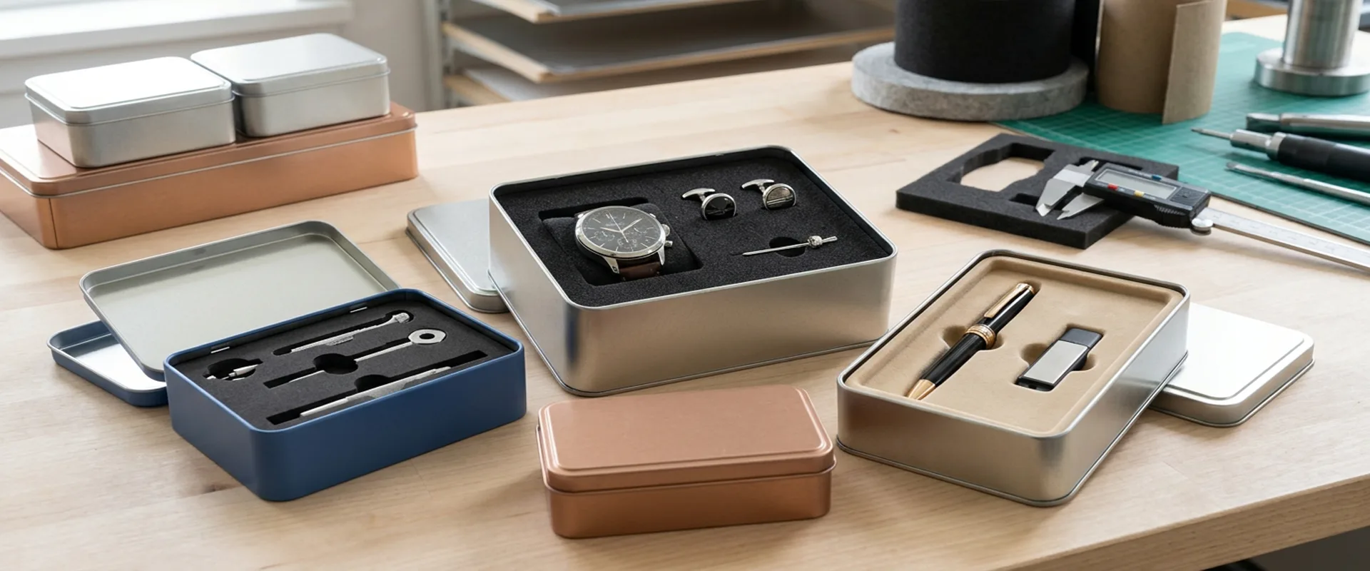
A custom tin box can have a well-designed exterior and still fail at the packing stage. The lid closes, the printed finish looks right, and the metal body meets the drawing dimensions. But the product sits too deep in its insert, the packing operator struggles to lift it out, or the insert rocks inside the box because its outside dimensions do not match the finished tin.
These problems are often traced back to the insert design rather than the tin itself. Custom tin box inserts must fit the product, the internal geometry of the metal box, and the packing method. Choosing a material based on appearance alone can create problems with retention, assembly time, surface protection, and production cost.
For gift sets, cosmetics, tea accessories, promotional items, and small components, the design work starts with three questions: What must the insert hold? How will the product be loaded and removed? What dimensional variation can the finished package tolerate?
This guide examines the material, geometry, fit, and production details that buyers should settle before approving a custom tin box insert.
Table of Contents
Choose the Insert Material Around the Product
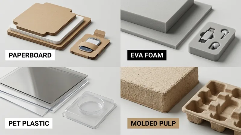
The material affects more than the appearance inside the box. It determines how the insert holds its shape, whether the product can be removed easily, how much clearance is needed, and how the package behaves during handling.
| Insert material | Typical applications | Main design concern |
|---|---|---|
| Paperboard | Gift sets, printed promotional packaging, lightweight products | Fold strength, panel deformation, and cavity retention |
| EVA foam | Selected electronics accessories, presentation kits, shaped products | Compression, odor, surface contact, and cavity fit |
| PET or other rigid plastics | Organized multi-item sets and repeatable cavity layouts | Edge finish, stiffness, scratching, and formed geometry |
| Molded pulp | Shaped fiber-based packaging and selected gift products | Surface texture, dimensional consistency, and cavity depth |
This comparison is a starting point, not a material specification. The actual grade, thickness, manufacturing process, and product-contact conditions matter.
Paperboard: Watch the folds and unsupported spans
Paperboard inserts are often suitable when the product is lightweight and the package needs a clean, organized layout. Die-cut lines define the cut geometry, while crease lines determine where the board folds. If these lines are poorly positioned, the assembled insert may bow outward, sit unevenly, or push against the tin walls.
The problem becomes more noticeable when several products are placed in adjacent cavities. Narrow dividers may bend during loading, particularly if the operator presses products into place at speed. A design that looks rigid in a flat drawing can behave differently after folding.
For a multi-piece gift set, check the assembled insert rather than judging only the flat cutting layout. Confirm that the partitions remain upright, the cavities stay open during loading, and the insert does not spring out of shape when the products are removed.
EVA foam: Fit and odor both matter
EVA foam can be useful for products that need shaped cavities and localized support. The cavity can follow the product outline, but the opening must account for the foam’s compression and recovery behavior.
An overly tight cavity may require the packing operator to press hard on the product. A loose cavity may allow movement even when the insert looks well fitted. Deep cavities can also make small items difficult to retrieve, especially when there is little room for the fingers to grip the product.
Material odor deserves attention when the package contains tea, coffee, cosmetics, or other odor-sensitive goods. EVA grades and manufacturing processes vary, so it is not accurate to assume that every foam insert will cause odor transfer. However, residual odor or volatile compounds can become a concern in an enclosed package. Buyers should request material information and evaluate representative samples under the intended storage conditions before using foam with odor-sensitive products.
Do not rely on the material name alone. A sample should be checked for odor, product contact, ease of removal, and any visible change to the product surface.
Rigid plastic: Inspect the edges, not just the cavity
PET and other rigid plastic inserts can provide consistent cavity shapes, especially for products arranged in a fixed pattern. However, the cavity geometry is only part of the design.
Cut edges, burrs, sharp corners, and excessive stiffness can create problems during assembly. If a rigid insert rubs against the tin’s interior coating, repeated movement may mark or scratch the finish. A plastic insert that fits tightly at the top but is poorly supported at the bottom can also rock inside the box.
Where the tin has a printed or coated interior, inspect the insert-to-wall contact points. The design may need additional clearance, rounded edges, or a different insert structure to prevent abrasion. A smooth-looking plastic surface does not automatically mean every edge is suitable for direct contact with a finished tin.
Measure the Finished Tin Before Designing the Insert
One common source of fit problems is designing the insert from the tin’s external dimensions. External length, width, and height do not tell the designer how much usable space remains inside the finished package.
Tinplate thickness, corner radii, folded edges, seams, and the lid construction all affect the internal envelope. On a rectangular tin, the internal corner radius may reduce the usable area near the corners. A rolled edge or an overlapping lid may also interfere with an insert that extends too high.
Use the finished tin’s internal dimensions as the starting point. If the box has not yet been manufactured, obtain the manufacturer’s internal dimensions and confirm the expected production tolerances.
The outer fit and the product cavity are two separate problems
The insert’s outside dimensions determine whether it fits inside the tin. The cavity dimensions determine how the product sits within the insert. These dimensions should not be treated as interchangeable.
Consider a rectangular tin with a measured usable internal length of 148 mm and an internal width of 98 mm. If the proposed insert measures 149 mm by 99 mm, it will interfere with the walls before the material’s flexibility is even considered.
A nominal clearance calculation can help identify this problem early:
Available clearance = Usable internal dimension − Insert external dimension
For example:
- Usable internal length: 148 mm
- Insert external length: 146 mm
- Nominal total clearance: 2 mm
This gives 2 mm of total clearance along the length, not 2 mm on each side. If the insert is centered, the nominal side clearance is approximately 1 mm per side.
This is only a preliminary calculation. It does not account for dimensional variation, corner geometry, insert deformation, or the way the insert is loaded into the tin. The appropriate clearance must be confirmed using the actual material and finished structure.
Corner radius and cavity layout
A rectangular insert with square corners may not sit properly inside a tin with a large internal R-angle, or corner radius. Depending on the geometry, the insert corners may contact the curved walls before the straight edges reach their intended positions.
Designers should compare the insert outline with the internal corner geometry rather than checking length and width alone. The same issue can arise around hinges, seams, and other features that intrude into the usable space.
For inserts made from folded paperboard, the assembled corner geometry also depends on crease placement and fold behavior. For molded inserts, the cavity and outside profile must be checked against the actual tooling design.
If the insert needs to sit flat at the bottom of the tin, verify the bottom contact area as well as the top opening. An insert that catches on the corners or rocks on the base may still fit within the nominal length and width measurements.
Design the Product Cavity for Loading and Removal
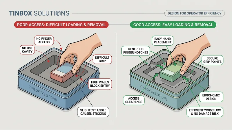
A cavity can hold a product securely but still be a poor production design if the product is difficult to load or remove. This is where packaging drawings need to account for the work performed by the packing operator.
A close-fitting cavity may be suitable for a product that is loaded mechanically or removed by pulling a defined tab. It may be impractical for a small product that must be placed by hand into a deep recess.
Finger notches and access clearance
Finger notches provide a gripping point so the user or packing operator can lift a product from its cavity. They are particularly useful for flat items, small accessories, and products that sit close to the top of an insert.
The notch must be large enough to provide access without weakening the surrounding material or compromising the presentation. On a foam insert, the notch can be cut into the cavity edge. In a rigid plastic design, the geometry must be compatible with the forming or molding process. Paperboard designs may use a cutout or folded feature.
The correct size depends on the product and the user’s grip. A notch that is visible in a drawing may still be ineffective if the adjacent cavity wall blocks finger access.
For a gift set containing several small items, review the loading sequence as well as the finished arrangement. If the operator must pinch each item at an awkward angle, rotate it several times, or press it below the cavity edge, the design may slow packing and increase the risk of cosmetic damage.
A practical sample review should therefore include repeated loading and removal, not just a single placement.
Draft angle and deep cavities
A draft angle is a slight taper built into a cavity wall to support release from tooling in molded manufacturing processes. It is particularly relevant to molded plastic and molded pulp inserts. The required angle depends on the material, cavity depth, surface texture, and manufacturing method.
A deep cavity with near-vertical walls may be difficult to release from a mold or may grip the product too tightly. Adding draft can improve manufacturability, but it also changes the cavity opening and the available support along the wall.
For this reason, the opening dimensions and the dimensions near the cavity bottom may differ. A product drawing should identify which section of the cavity controls the fit, especially when the product has tapered sides or a stepped profile.
Draft angle is not a universal requirement for every insert. Cut foam and folded paperboard use different manufacturing methods, so their design constraints should be assessed separately.
Understand Fit Tolerance and Tolerance Stack-Up
The nominal dimensions of the tin, insert, and product do not tell the whole story. Each component has manufacturing variation, and those variations can accumulate in the assembled package. This is known as tolerance stack-up.
Suppose a tin’s usable internal width varies between production units, while the insert’s outside width also varies due to cutting, folding, molding, or material recovery. An insert designed to fit one sample perfectly may be too tight in a smaller tin and too loose in a larger one.
The same principle applies to the product cavity. A cavity designed around the nominal product size may not accommodate the largest acceptable product or retain the smallest one. The result can be inconsistent packing conditions across the order.
A practical way to review the fit
Start by identifying the dimensions that control assembly: the tin’s internal length and width, the insert’s external dimensions, the product’s maximum envelope, and the cavity’s controlling dimensions.
Next, obtain the applicable manufacturing tolerances for those features. Where the insert must fit inside the tin, compare the largest insert with the smallest permitted internal space. Where the product must enter the cavity, compare the largest product with the smallest permitted cavity opening.
For a simple rigid fit, the worst-case minimum clearance can be expressed as:
Minimum clearance = Minimum internal dimension − Maximum insert dimension
If the minimum internal width is 97.5 mm and the maximum insert width is 97.8 mm, the minimum clearance is −0.3 mm. This indicates a 0.3 mm interference under that worst-case combination.
That result does not automatically mean the design will fail. Flexible materials can compress, and some structures are intentionally designed with interference. But the designer must confirm that the material can accommodate the condition without buckling, damaging the tin finish, or making assembly difficult.
The calculation is useful because it reveals what needs testing. It does not replace a physical fit check, particularly when the insert is folded, flexible, molded, or affected by humidity and temperature.
Prevent Surface Damage Inside the Tin

The inside of a tin box is not always bare metal. It may have a protective coating, printed graphics, or a decorative finish. An insert that moves during transportation can rub against these surfaces, leaving marks that become visible when the box is opened.
Rigid plastic edges deserve particular attention. If the insert has sharp corners or cut edges, vibration and repeated movement may cause localized abrasion. Increasing the clearance can reduce pressure at some contact points, but too much clearance may allow the insert to move farther during handling. The solution may involve edge finishing, rounded corners, better seating, or a different insert material.
Foam and fiber-based materials introduce different considerations. Foam should be checked for surface compatibility and odor. Paperboard should be checked for loose fibers, exposed cut edges, and any transfer to the product or interior finish. Molded pulp has a more textured surface, which may not suit every delicate product.
The appropriate test depends on the package. For a coated tin, inspect the interior after repeated insertion and removal of the insert. For a product with a sensitive finish, inspect the contact areas for scratches, residue, or pressure marks. If the package will be transported, assess whether vibration or movement causes the insert to rub against the tin.
A fit check that examines only whether the insert can be placed inside the box will miss these issues.
Match the Insert Design to the Packing Process
Insert geometry affects packing speed. A cavity may be dimensionally correct yet awkward to use if the operator cannot identify the correct orientation, grip the product easily, or load several components in a consistent sequence.
For example, a gift set with a main product and two accessories may require the accessories to be placed first so that they do not obstruct the main cavity. If the insert makes the sequence unclear, operators may repeatedly remove and reposition components. At higher volumes, these small interruptions can become a meaningful labor cost.
The layout should allow the product to enter the cavity without excessive force and remain stable when the box is moved to the next packing step. Finger notches, tapered cavity walls, clear orientation features, and sufficient access around the product can help, provided they do not weaken the insert or compromise the appearance.
The lid must also close without pressing against the product or insert. A tall product, a raised cavity, or a flexible insert that bulges under load can reduce the available headroom. Check the assembled package with all contents in place rather than evaluating the insert separately.
A useful production trial is to have the intended packing method performed repeatedly with representative samples. Observe where the operator hesitates, where the product catches, and whether the insert shifts during loading. Those observations often reveal more about usability than the drawing alone.
Estimate Tooling and Production Cost Before Finalizing the Design
The cost of custom tin box inserts includes more than the material. Cutting, folding, molding, assembly, tooling, and inspection can all contribute to the total cost.
A folded paperboard insert may require less initial tooling than a molded plastic insert, but it can involve more manual assembly. A molded design may provide repeatable cavity geometry but require dedicated tooling. Foam can be suitable for a complex product outline, although the cutting method and material thickness affect cost and production time.
The comparison changes with order quantity. For a small run, a simple insert with modest setup requirements may be more economical. For a larger order, a design that reduces manual handling or makes packing more consistent may justify a higher initial investment.
Avoid adding cavities and decorative features that do not serve a clear purpose. More compartments can improve product organization, but they may also require thinner dividers, more complex tooling, and a slower loading sequence. Every feature should have a functional or presentation reason.
When requesting a quotation, provide the expected order quantity, the number of products per box, the proposed material, and the required packing method. If the material has not been selected, ask for alternatives with their respective tooling and recurring production implications.
What to Include in a Custom Tin Box Insert RFQ
A useful RFQ gives the manufacturer enough information to assess the insert and tin as one assembly. Include the product’s dimensions, weight, shape, surface finish, and quantity per package. Product drawings are preferable where dimensions are critical; photographs can help explain orientation and presentation.
Provide the tin’s external dimensions, structure, and confirmed internal dimensions if available. If the tin is still being developed, state that the insert dimensions must be finalized against the approved box design. This prevents the insert from being released using an internal space estimate that may change later.
The RFQ should also explain the intended use. A retail gift box, a promotional kit, and a package for fragile accessories may have different requirements for product presentation, retention, and transportation. State whether the package will be shipped as a finished unit and whether the product must be easy to remove after opening.
Finally, identify the expected quantity, material preference, finish requirements, and sample approval process. If a reference insert exists, provide it along with its dimensions and any known problems. A physical sample can clarify the desired result, but it should be checked against the production dimensions rather than copied without review.
FAQ
What is the best material for custom tin box inserts?
Paperboard is suitable for many lightweight gift sets, EVA foam can support selected products that need shaped cavities, rigid plastic can provide defined compartment geometry, and molded pulp can suit certain fiber-based packaging designs. The choice depends on the product, surface sensitivity, required fit, order quantity, and packing method.
How do I calculate custom tin box insert dimensions?
Start with the usable internal dimensions of the finished tin. Subtract the insert’s external dimensions to estimate the nominal clearance, then review the manufacturing tolerances and corner geometry. Calculate product cavity dimensions separately, using the product’s actual envelope and the required insertion and removal clearance.
Can a foam insert affect tea or other odor-sensitive products?
It can be a concern if the selected foam has residual odor or releases compounds that affect the packaged product. This is not true of every foam grade. For tea, coffee, or other odor-sensitive goods, obtain material information and assess the actual insert under representative packaging and storage conditions.
Why can a plastic insert scratch a tin box?
Sharp cut edges, excessive stiffness, and repeated movement can cause an insert to rub against the tin’s interior coating. Edge finishing, suitable clearance, stable seating, and sample testing can help identify whether the proposed design creates an abrasion risk.
What is tolerance stack-up in insert design?
Tolerance stack-up is the combined effect of dimensional variation across the tin, insert, and product. It can cause an insert to fit some boxes while interfering with others, or allow products to move in cavities that are too large. Reviewing worst-case dimensions helps identify these risks before production.
Do custom tin box inserts require tooling?
Not always. Some paperboard and cut-foam inserts can be produced without the same level of dedicated tooling required by molded plastic or molded pulp structures. The method depends on the material, geometry, quantity, and required dimensional consistency.
Should the insert be tested before mass production?
Yes, when fit, product protection, surface finish, or packing efficiency is important. Evaluate the insert with the actual product and a representative finished tin. Check loading, removal, lid closure, internal surface contact, and movement during handling before approving the production design.