

Tin packaging requirements need to be defined before a custom tin packaging project moves into production engineering. A buyer may start with a target size, filling volume, product weight, lid style, artwork, or a reference sample. Production then needs to turn those requirements into a workable combination of material, dimensions, forming operations, tooling, tolerances, and finishing processes.
Problems usually appear when one requirement is defined without considering the parts around it. Changing tinplate thickness can change springback and forming behavior. Changing the body diameter changes the lid fit. Increasing embossing depth can affect the surrounding panel. Tightening a tolerance on a formed dimension can require additional tooling adjustment and inspection.
The specification therefore needs to describe the parts that control production, not just the final appearance. The tin packaging requirements should connect the product structure, material, dimensions, functional tolerances, tooling, surface treatment, and inspection conditions into one production reference.
Table of Contents
Tin Packaging Requirements for Dimensions and Internal Capacity
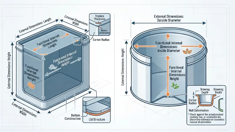
The basic dimensions depend on the package shape.
A rectangular tin normally uses length, width, and height. A round tin uses outside diameter and height. These dimensions describe the finished body, but they do not define the usable internal space.
Tinplate thickness, corner radius, bottom construction, lid structure, and forming depth all reduce the available internal volume. If the package must hold a specific quantity of cookies, tea, powder, cosmetic product, or small components, the internal dimensions should be checked against the actual product rather than estimated from the outside dimensions.
Deep-drawn bodies also require attention to the relationship between blank size, drawing depth, corner radius, and wall deformation. A design that looks acceptable in CAD may require changes to the forming sequence when the drawing depth becomes large or the corners become too tight.
The drawing should distinguish between external dimensions and functional internal dimensions. Both can affect the final package.
Tinplate Thickness and Material Condition
Material selection affects the forming process directly.
Tinplate thickness influences stiffness, weight, bending behavior, drawing behavior, and the final dimensions after forming. A change in thickness also changes the clearance relationship between the punch and die.
Temper affects hardness and elongation. Harder material may hold a formed shape differently from softer material, while softer material can be more suitable for certain drawing or forming operations. Springback also changes with material condition and forming geometry.
The material specification should therefore identify the tinplate type, thickness, temper, and grade when these parameters have already been established.
Surface condition matters when the sheet will go through printing, coating, embossing, or deep forming. Oil, contamination, scratches, coating variation, or surface damage on the incoming sheet can become visible after forming.
Material changes should not be treated as a simple purchasing substitution. A different thickness or temper can require changes to forming parameters or tooling clearance.
Body and Lid Construction
The structure of the tin determines how the parts will be formed and assembled.
A basic container may use a body, bottom, and separate lid. Other constructions use slip lids, friction-fit lids, hinged lids, double-wall structures, or additional formed components.
Each structure creates different dimensional relationships.
A friction-fit lid depends on the relationship between the body opening, lid diameter, curl dimensions, material thickness, and forming accuracy. A hinged lid adds hinge alignment and movement requirements. A deep-drawn body may require multiple drawing or forming stages when the depth and geometry exceed the capability of a single operation.
Embossed panels also affect the forming layout. The location of an embossed logo or recessed area should leave enough material around corners, seams, curls, and other formed features.
The final drawing should show the actual construction. A rendered image or reference sample can describe the appearance, but it cannot replace dimensions and section details.
Lid Fit and Closure Tolerance
Lid fit is controlled by several dimensions at the same time.
For a friction-fit lid, the body opening, lid diameter, curl diameter, curl height, and material thickness all contribute to the final fit. A small change in one dimension can change the opening force.
A loose lid may move during handling. Excessive interference can make the lid difficult to remove or cause deformation around the curl.
This is where nominal dimensions alone become insufficient. The manufacturer needs the functional dimensions and their allowable ranges.
For hinged tins, the hinge position, hinge width, curled sections, lid alignment, and body geometry control the opening movement. Burrs or deformation around the hinge area can also affect assembly.
If the customer has an opening-force or closing-force requirement, it should be defined before sample approval. Otherwise, the manufacturer can only evaluate the fit against the drawing and the agreed sample.
Functional Dimensions and Tolerances
Not every dimension needs the same tolerance.
The body height of a decorative tin may tolerate a wider range than the diameter controlling a friction-fit lid. A hinge position may have a tighter functional requirement than the overall panel width. A hole location may need tighter control because another component references it.
The drawing should therefore separate functional dimensions from general dimensions.
Formed dimensions also behave differently from machined dimensions. Stamping and drawing introduce springback, material movement, tool clearance effects, and local deformation. The final measurement can therefore differ from the tool dimension.
Overly tight tolerances can create unnecessary tooling adjustments and inspection work. Loose tolerances can cause assembly or functional problems. The practical tolerance range should follow the function of the feature and the capability of the forming process.
Forming, Drawing, and Springback
The package geometry needs to match the forming process.
Shallow stamped parts usually have different forming requirements from deep-drawn bodies. Drawing depth, corner radius, wall height, blank size, and material temper affect the forming load and the risk of wrinkles or cracking.
Springback can shift the final angle or dimension after the material leaves the tool. This matters when several formed parts must fit together.
For example, a body sidewall can return slightly after forming, changing the opening dimension. A bent hinge section can also move after unloading. Tool compensation may be required once the actual material and forming behavior have been confirmed.
Embossing introduces another local forming condition. Deep embossing can stretch the material around the feature and affect the flatness of the surrounding panel.
These conditions should be reviewed before the tooling dimensions are locked.
Surface Finish, Coating, and Printing

Surface requirements need to match the production sequence.
A tin package may receive internal or external coating, base coating, color printing, protective varnish, embossing, debossing, or a combination of these processes.
Printing registration becomes more complicated when the printed sheet later goes through stamping or drawing. The artwork position must account for the forming area and the final panel geometry. A graphic that is centered on the flat sheet may not remain centered after forming if the design does not account for material movement.
Color variation also needs a defined reference. For repeat production, the artwork file, color reference, printing sequence, and registration tolerance should remain consistent.
Coating damage can occur during forming when the tool surface, clearance, lubrication, or material condition is not controlled. Scratches, exposed metal, coating cracks, and local surface marks should be identified during sample inspection rather than discovered after a production run.
Burrs, Seams, and Cut Edges
Cutting operations create another set of production requirements.
Burr direction and burr height matter when the edge becomes part of an assembly or a consumer-accessible area. Excessive burrs can interfere with lid movement, hinge assembly, or handling.
Seamed bodies also require control of the joint geometry. The seam position should not interfere with the lid, artwork, embossing, or other functional features.
When the package uses curled edges, the cut edge, curl diameter, curl height, and material thickness work together. A change in one parameter can alter the final edge condition.
These details often do not appear in a simple product rendering, but they belong in the manufacturing specification when they affect assembly or safety.
Product Requirements and Package Performance
The specification should describe the actual job of the package.
If the tin holds food, the material and coating system need to match the intended food-contact application. If the contents contain oils, powders, acids, or other substances that interact with the internal surface, the internal coating requirement should reflect the product.
A cosmetic tin may need a different internal coating or closure arrangement from a cookie tin. A tin used for small industrial components may place more emphasis on dimensional compatibility and repeated opening and closing.
Stacking, handling, filling method, product insertion, and removal can also affect the package design.
A statement such as “good sealing” does not define a production condition. A defined lid fit, closure force, internal dimension, coating specification, or inspection method gives the production team something measurable.
Drawings, CAD Files, and Artwork
A 2D production drawing provides the dimensional reference. It should include the relevant dimensions, tolerances, material, thickness, surface treatment, and functional features.
A 3D CAD model helps the tooling engineer review the overall geometry, especially when the tin contains formed corners, embossed areas, deep-drawn sections, or multiple components.
Artwork files serve a different purpose. They define printing content, color information, registration, and the position of graphics on the panels.
The three should match.
A common problem occurs when the CAD model shows one dimension, the 2D drawing shows another, and the artwork was prepared from an earlier version. The discrepancy may not appear until tooling or sampling begins.
Revision control should therefore be clear before tooling starts.
Tooling Requirements

The final specification has a direct effect on die construction.
A shallow rectangular tin may require relatively simple stamping and forming operations. A deep-drawn body, embossed surface, complex corner, or special lid can require several forming stages.
The tooling engineer needs to consider punch and die geometry, clearance, forming radius, material thickness, blank size, and the sequence of operations.
Tool clearance cannot be selected independently of the material. A change in tinplate thickness can change the forming condition. A tight radius can increase the risk of cracking, while an unsuitable forming condition can create wrinkles or dimensional instability.
Curling tools require similar attention. The tool geometry controls the finished curl and therefore influences lid fit, edge condition, and assembly.
Tooling should be reviewed against the production drawing rather than against a visual sample alone.
Prototype and Sample Approval
The first sample checks the assumptions made during design and tooling.
Dimensional inspection can identify variation in body size, height, lid diameter, curl dimensions, hinge position, and other functional features. Assembly checks show whether the lid fits as intended and whether the components move or close correctly.
Surface inspection should cover scratches, coating damage, printing registration, embossing position, and other visible defects.
The sample may reveal springback or forming behavior that was not obvious from the CAD model. Tool adjustment can then compensate for the measured condition.
Once the sample is approved, the approved drawing, material specification, artwork, surface requirements, and inspection criteria should become the production reference.
Managing Changes Before Mass Production
Changes become more expensive once tooling and sampling have started.
A change to the body diameter can require a corresponding change to the lid. A change in material thickness can affect the forming clearance. A deeper emboss may require a tooling modification. Moving a printed graphic may require a new artwork proof without changing the metal part itself.
The effect of each change should therefore be checked against the related components and processes.
A useful production specification does not try to define every possible detail at the beginning. It defines the dimensions and conditions that control function, forming, assembly, surface treatment, and inspection. The remaining details can then be confirmed during tooling and sampling.
Frequently Asked Questions
What information should a tin packaging drawing contain?
The drawing should normally identify the main dimensions, functional dimensions, tolerances, material, thickness, structure, lid or closure requirements, and relevant surface or forming features.
How does tinplate thickness affect the package design?
Thickness affects stiffness, forming behavior, springback, tool clearance, weight, and the relationship between mating components. A thickness change should be reviewed before production rather than treated as a simple material substitution.
Which dimensions usually require tighter control?
Dimensions that control lid fit, hinge alignment, assembly, or the position of another component generally require closer control than non-functional external dimensions.
Can the manufacturer recommend material and tolerances?
Yes. When the customer has not fixed the material or tolerance range, the manufacturer can review the package geometry, forming process, closure structure, and production volume and then define practical production conditions.
What should be approved before mass production?
The approved reference should normally cover the physical sample, production drawing, material specification, artwork, surface requirements, functional dimensions, and inspection criteria. These references provide the basis for checking subsequent production.