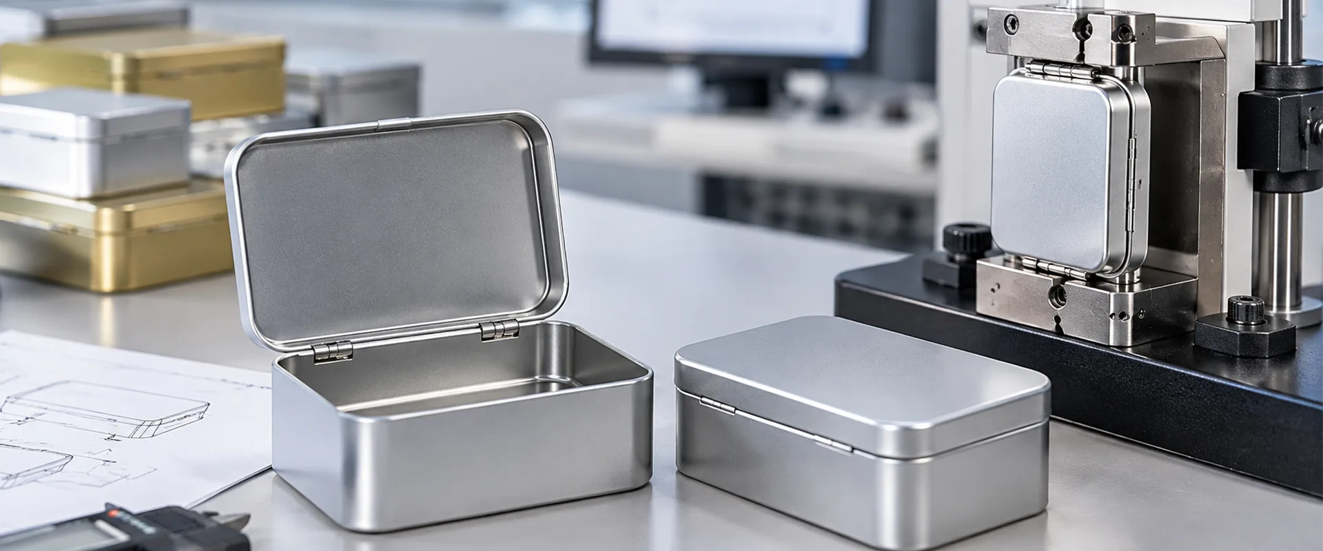
Hinged tin boxes combine a metal body, a lid, and a hinge mechanism that allows repeated opening and closing without separating the lid from the container. Their performance depends on more than the hinge itself. Hinge position, sheet-metal forming, lid geometry, attachment strength, and assembly tolerances all affect how the finished box operates.
For manufacturers developing custom hinged tin boxes, the main engineering task is to keep the lid aligned with the body while allowing the hinge to move freely. A hinge that operates correctly on the first sample may behave differently after repeated use or when small dimensional variations accumulate during mass production.
This article explains the main considerations in metal tin box hinge design, including hinge construction, lid alignment, material deformation, durability testing, and production inspection.
Table of Contents
Hinged Tin Box Structures and Hinge Types
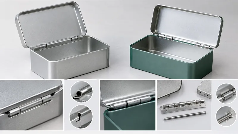
A hinged tin box generally consists of a formed tinplate body, a lid, and a connection that controls the movement of the lid. The construction method determines the assembly process, the available opening angle, and the points that require inspection.
Integrated Metal Hinges
An integrated metal hinge uses formed features on the lid and body to create the pivoting connection. Depending on the design, these features may include interlocking tabs, rolled knuckles, or other formed sections that engage around a pivot axis.
This construction reduces the number of separate components, but it requires consistent forming and positioning. If the hinge features are not aligned, the lid may move unevenly, bind during opening, or sit at an angle when closed.
The design should define the hinge profile, engagement length, pivot position, and clearance between moving parts. These dimensions must be considered together rather than specified independently.
Separate-Pin Hinges
Some hinged metal boxes use separate hinge components or a pin to connect the lid and body. This arrangement may provide a defined pivot axis, but it introduces additional assembly variables.
Pin diameter, hinge knuckle alignment, axial clearance, and retention method can influence movement. Excessive clearance may allow the lid to shift from side to side, while insufficient clearance can increase friction or cause binding.
The attachment method also matters. The hinge must remain secure under repeated opening and closing without causing unacceptable distortion in the surrounding tinplate.
Selecting the Hinge Structure
Hinge selection should begin with the required operating conditions rather than appearance alone.
A small tin box used for occasional storage may have different requirements from a container opened several times each day. Lid weight, box dimensions, opening angle, expected cycle count, and the way the user handles the lid should all be considered during design.
The product drawing should identify the hinge construction and the critical dimensions needed for assembly and inspection. A general note such as “metal hinge” is not sufficient to control the finished geometry.
Hinge Position and Tin Box Lid Alignment
Tin box lid alignment is one of the main indicators of hinge assembly quality. A lid can appear acceptable when the box is open but become visibly misaligned when it is closed.
The hinge establishes the lid’s movement path. If its axis is offset or tilted relative to the intended position, the lid may rotate unevenly, contact the body at one corner, or leave an inconsistent gap along the closing edge.
Pivot Axis and Hinge Location
The pivot axis should be defined relative to stable body and lid reference surfaces. These references allow the hinge position to be checked during tooling development, sample approval, and production inspection.
For a rectangular hinged tin box, the following dimensions may require control:
- Distance from the hinge axis to the rear body edge.
- Position of the hinge attachment features.
- Alignment between the lid and body hinge sections.
- Side clearance between the lid and body.
- Lid-to-body overlap at the front and side edges.
The relevant dimensions depend on the hinge design and box geometry. Not every design requires a separate tolerance for every feature, but the drawing should identify the dimensions that directly affect movement and closure.
Clearance Between the Lid and Body
The lid and body need sufficient clearance to move without interference. However, excessive clearance can make the lid appear loose or produce uneven gaps when closed.
Clearance is affected by several factors, including tinplate thickness, formed edge geometry, corner radius, lid overlap, and springback after bending. The hinge adds another variable because its position controls the lid’s rotational path.
For this reason, the lid and body should be evaluated as an assembled unit. Measuring each component separately does not always reveal interference that occurs during rotation.
A practical inspection should check the lid at several positions: fully closed, partially open, and near the intended maximum opening angle. This helps identify contact points that may not be visible in a closed-box inspection.
Tinplate Thickness, Forming, and Hinge Deformation
Tinplate thickness and temper affect the way hinge features can be formed and how they respond to repeated movement. The material specification should be selected alongside the hinge geometry and the forming process.
A hinge feature that is too small or sharply formed for the selected material may be difficult to manufacture consistently. Conversely, a hinge designed without considering the available forming process may require excessive adjustment during assembly.
Forming Accuracy and Springback
Springback occurs when formed sheet metal partially returns toward its original shape after the forming load is removed. Its magnitude depends on material properties, thickness, geometry, and process conditions.
At a hinge, springback can change the angle or position of formed tabs and knuckles. Small differences may affect engagement, pivot clearance, or the alignment of the lid with the body.
Tooling trials should therefore verify the finished hinge geometry after forming, not only the dimensions of the tooling itself. If adjustment is necessary, changes should be evaluated against the complete assembly.
Deformation Around Attachment Points
Hinge attachment areas can experience localized stress during assembly and use. Excessive forming pressure, poor support during fastening, or repeated loading may deform the nearby panel.
Potential symptoms include:
- A bent or twisted hinge section.
- Cracking or tearing at a formed feature.
- A loose pivot or attachment point.
- Permanent deformation of the rear lid edge.
- A change in lid alignment after repeated use.
The inspection method should distinguish between an assembly defect and damage introduced during subsequent handling. This distinction matters when determining whether the cause lies in tooling, assembly settings, material condition, or packaging.
Coating and Printed Surface Protection
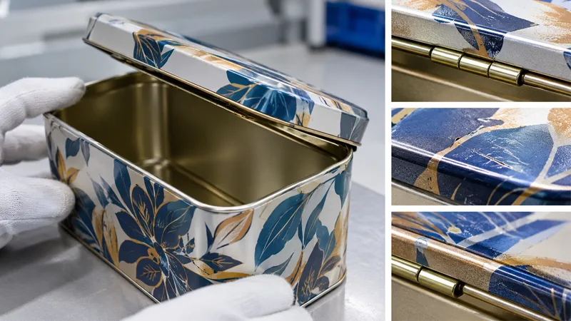
Printed tinplate may have an exterior protective coating over the printed design. Hinge forming and assembly can create localized contact or abrasion, especially around edges and moving components.
The design should account for the contact surfaces and the movement path of the hinge. Tooling condition, handling methods, and assembly fixtures should be reviewed if scratches, coating damage, or exposed metal appear near the hinge.
Inspection should include both the mechanical connection and the surrounding printed surface. A hinge that operates correctly can still leave the product outside the approved appearance standard if the adjacent coating is damaged.
Opening Angle, Movement, and Closure Behavior
The required opening angle should be established before the hinge geometry is finalized. A lid intended to open only far enough for product access may need different movement limits from a lid designed to remain open while the user retrieves small items.
Opening Angle and Clearance
The maximum opening angle depends on hinge geometry, lid shape, the rear edge of the body, and any contact between the lid and surrounding surfaces.
If the lid contacts the body before reaching the intended position, the contact point may concentrate force on the hinge or rear panel. Repeated operation can then produce deformation or a change in the opening path.
The design should identify the intended operating range and any mechanical stop or contact surface that limits movement. The hinge should not rely on an unintended collision between thin sheet-metal edges to control the opening angle.
Opening and Closing Force
The force required to move the lid depends on friction, pivot clearance, hinge geometry, lid weight, and any retention or closing features.
A high opening force may indicate binding, interference, misalignment, or excessive friction. A very low force may indicate loose engagement or a hinge that does not maintain its intended position.
There is no single opening-force value suitable for every hinged tin box. Acceptance limits should be established for the specific design and assessed using a consistent method. If force is measured, the test should define the point of application, direction of force, lid position, and measuring equipment.
Lid Position After Opening
Some designs are intended to remain open at a defined angle, while others allow the lid to move freely. These are different functional requirements and should not be treated as interchangeable.
Where the lid must remain open, the design needs a mechanism or geometry capable of maintaining that position under the specified conditions. A simple pivot hinge should not automatically be assumed to provide a stable open position.
Hinged Tin Box Durability Testing
Hinged tin box durability testing evaluates whether the hinge continues to perform its intended function after repeated opening and closing. The test should reproduce the expected operating movement as consistently as possible.
A cycle count by itself does not define a complete test. The movement speed, opening angle, handling force, rest intervals, and inspection criteria can all influence the result.
Establishing the Test Method
Before testing, document the following conditions:
- The approved sample or production lot used for the test.
- The starting condition of the hinge and lid.
- The opening angle or movement limit.
- The method used to open and close the lid.
- The required number of cycles.
- The inspection intervals and acceptance criteria.
The cycle requirement should be based on the intended use, customer specification, and product risk. It should not be selected solely because a particular number is common in another application.
For example, a tin box intended for occasional access may require a different test plan from a box expected to be opened multiple times per day. Where no customer standard exists, the manufacturer and customer should agree on a documented internal test protocol.
Inspecting the Hinge During the Test
Inspection should occur before testing, at defined intervals, and after the final cycle. Intermediate checks help identify when a change first appears rather than revealing only the final failure condition.
Record any change in:
- Opening and closing movement.
- Hinge attachment stability.
- Lid alignment and closing gap.
- Side-to-side movement at the pivot.
- Deformation around the hinge.
- Cracking, tearing, or visible coating damage.
If the hinge begins to bind, the test should not continue blindly until the target cycle count is reached. The condition should be documented, and the sample should be examined to determine whether the issue is caused by interference, deformation, wear, or a test setup problem.
Pass and Fail Criteria
Acceptance criteria should be defined before testing begins. Depending on the design, the criteria may include completion of the specified cycle count, no hinge separation, no unacceptable deformation, acceptable lid alignment, and continued opening and closing within the agreed functional limits.
A sample that completes the required cycles but develops a loose hinge or a lid that no longer closes correctly should not automatically be considered acceptable.
Test reports should identify the sample, material specification, hinge design, test conditions, cycle count, observations, and final result. Photographs of the initial and final conditions can help compare changes between samples or production lots.
Production Inspection for Custom Hinged Tin Boxes
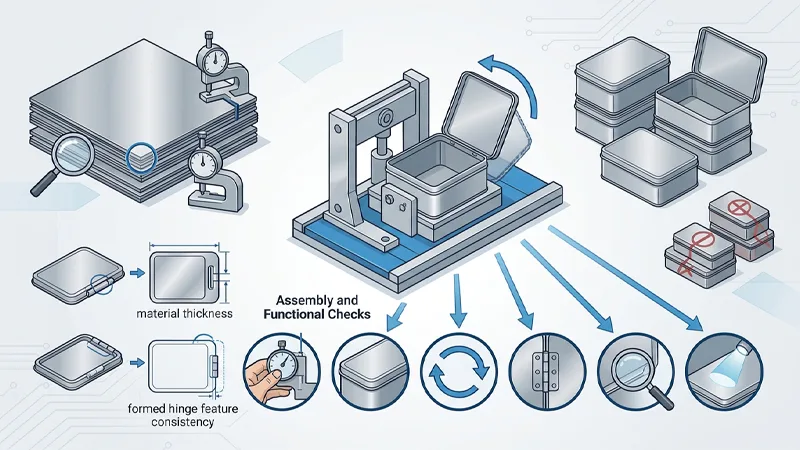
A successful prototype does not guarantee that every unit in a production run will perform identically. Variation can enter through material thickness, forming, hinge attachment, fixture positioning, and manual assembly.
Production inspection should therefore focus on the features that control function and alignment.
Incoming Material and Formed Components
Confirm the specified tinplate grade, thickness, and material condition. During the initial production review, check whether the formed hinge features remain consistent with the approved sample and drawing.
Where the process uses separate hinge parts or pins, verify the relevant component dimensions and condition before assembly. Burrs, deformation, or inconsistent component geometry can affect movement and attachment.
Assembly and Functional Checks
The assembly fixture should locate the lid and body consistently while the hinge is attached. If the components shift during fastening, the resulting hinge position may vary across the batch.
Useful production checks include:
- Hinge position relative to the defined reference surfaces.
- Lid alignment when fully closed.
- Opening and closing movement.
- Attachment stability.
- Visible deformation around the hinge.
- Surface damage near formed or moving areas.
The sampling plan should reflect the risk of the hinge failure and the stability of the production process. Initial production runs, tooling changes, material changes, or assembly adjustments may require additional verification.
Defect Records and Corrective Action
When a hinge defect is found, record the failure mode rather than using a general description such as “bad hinge.” Terms such as pivot binding, loose attachment, lid skew, hinge-tab deformation, and rear-panel distortion provide more useful information for root-cause analysis.
The investigation should compare the defective sample with an approved sample and review the relevant process settings, tooling condition, and assembly sequence. Any corrective action should be verified on subsequent samples before the revised process is treated as stable.
Common Hinged Tin Box Problems and Their Causes
The same symptom can have more than one cause. The following table provides a starting point for investigation rather than a substitute for checking the actual part.
| Observed problem | Possible causes | Inspection focus |
|---|---|---|
| Lid sits unevenly when closed | Hinge axis misalignment, uneven forming, body distortion | Compare lid edges and hinge reference positions |
| Lid binds during opening | Insufficient clearance, pivot misalignment, interference | Check movement at different opening angles |
| Hinge becomes loose | Inadequate engagement, attachment variation, wear | Inspect pivot clearance and attachment condition |
| Rear panel bends | Excessive force, poor support during assembly, unintended lid contact | Examine deformation and contact marks |
| Lid opens beyond the intended range | Hinge geometry or stop position does not control travel | Verify opening angle and limiting surfaces |
| Coating is scratched near the hinge | Contact between moving parts, burrs, tooling or handling damage | Inspect contact areas and the assembly process |
| Hinge features crack or tear | Unsuitable geometry, material condition, forming damage | Review formed radii, material specification, and process condition |
Corrective action should address the cause rather than simply forcing the lid back into alignment. Manual adjustment may conceal a dimensional problem without preventing it from recurring during mass production.
Design Information Required Before Production
To evaluate a new hinged tin box, the manufacturer needs enough information to define the geometry, assembly process, and inspection requirements.
A useful design package includes the following:
- Overall body and lid dimensions.
- Tinplate thickness and material specification.
- Hinge type and attachment method.
- Required opening angle and movement behavior.
- Lid alignment and closure requirements.
- Exterior printing and coating specifications.
- Expected use conditions and durability requirements.
- Applicable dimensional, appearance, and functional acceptance criteria.
A physical reference sample can help clarify movement and appearance, but it should not replace controlled drawings when critical dimensions must be maintained across production batches.
When the design is still being developed, hinge geometry, lid clearance, and assembly access should be reviewed together. Changing the hinge position after tooling or artwork has been finalized may affect adjacent forming features, printed panels, and the fit between the lid and body.
Conclusion
The performance of hinged tin boxes depends on the relationship between hinge geometry, tinplate forming, assembly accuracy, and repeated movement. A hinge that operates correctly on an initial sample may still develop alignment or attachment problems if dimensional variation is not controlled during production.
Defining the pivot position, lid clearance, opening range, durability test method, and inspection criteria before mass production provides a consistent basis for evaluating the finished box. When a defect occurs, the investigation should identify whether it originated in material condition, tooling, forming, assembly, or subsequent handling.
Frequently Asked Questions
What should be checked when designing custom hinged tin boxes?
Check the hinge type, pivot position, attachment method, lid clearance, opening angle, and the dimensions that control alignment. The design should also define how the hinge will be inspected after assembly and what constitutes acceptable movement.
Why does a hinged tin box lid become misaligned?
Possible causes include an incorrectly positioned hinge, uneven forming, springback, body distortion, or variation during assembly. The lid and body should be inspected as an assembled unit to identify where the misalignment originates.
How is hinged tin box durability tested?
A documented test repeatedly opens and closes the lid under defined conditions. The test plan should specify the movement range, cycle count, inspection intervals, and acceptance criteria. Results should include both functional observations and any changes in hinge or lid geometry.
What causes a metal tin box hinge to become loose?
Possible causes include inadequate engagement, excessive clearance, deformation around the attachment points, or wear during repeated use. The specific cause should be determined by examining the pivot, attachment features, and surrounding tinplate.
Can printed tinplate be damaged around the hinge?
Yes. Forming, assembly, friction, or contact between moving parts can damage the printed or coated surface near the hinge. The design and production process should control contact points and include visual inspection of these areas.